|
||
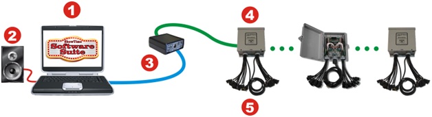
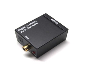
Technical SpecificationsWe use LOR lighting controllers from LightORama. This year we will use approx 30 CTB16PC lighting controllers. Some of these are visible from the street as they are mounted within the confines of our display. Most of these are mounted indoors in our garage or basement. Since each controller can operate 16 channels we have capability of 480 channels. We use over 450 individual channels in our display. Our display is driven from an 8GB dual display quad core desktop computer in the house. From this computer, the audio is output digitally then converted back to analog at the FM transmitter located in the garage. This is done to insure audio high fidelity and audio purity. An external antenna is utilized to radiate the RF signal from the transmitter. The lighting signal is output from a USB 2.0 port to a LOR converter that converts the signal to the LOR protocol. It is then fed to each lighting controller in a simple ‘daisy chain’. Since each controller is uniquely addressable, they can all be daisy chained together with simple Ethernet cables. A very basic diagram on how this all works can be seen below. 1) Any computer can be used using a Windows operating system.
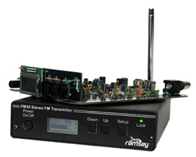
You must run the LOR software called S2 or S3. Electricity is fed from four separate sources to power our display. Because most of the lights are actually off while a song is playing electricity usage is kept at a minimum. Only during the ‘grand finale’ of a song are most of the lights illuminated and that’s when I need power to be fed from four separate electrical circuits. To reduce installation time I designed many ‘harnesses’ that are used to easily and quickly hook up our main display components. If I didn’t do this I would need 450 separate ‘extension cords’ to hook everything up. Currently over two miles of wire is used to hook up all of our various 'elements' to their LOR controllers. A high quality Ramsey FM transmitter is used to broadcast the FM audio signal to your car. Commercial quality connections are used between the D/A converter and the transmitter. Because a Ľ wave external antenna is utilized, only 1 milliwatt of RF power is used which is sufficient enough to broadcast 1-2 houses away from my home. To maintain reliability, I have backups ‘standing by’ for most everything used in our display should an electronic failure occur.
Audio Ducking We use a professional audio ducker in the audio line so that we can talk over the show audio for the purpose of emergency or safety announcements this also gives us the ability to do karaoke should someone want to sing over the songs. Any takers? D/A and A/D conversions. The audio output signal is sent from the computer in the ‘digital domain’. It is sent out on a ‘Toslink’ fiber optic cable from the back of the computer that is immune from all electrical interference. Just inches from the transmitter, this ‘digital’ signal is converted back into an analog electrical stereo signal (left & right) by a D/A converter where it is then fed through the ‘ducker’ and daisy chained to both the transmitter and the input of an audio amplifier that is used for local outdoor speakers. This process of D/A and A/D conversion ensures a high fidelity ‘clean’ audio signal that is free from noise and static. Energy Management. Even though we will exceed 110,000 LED’s this year, Energy consumption has to be monitored and carefully controlled. Everything is designed for ‘worst case scenario’ so that if all the lights accidently came on at once and stayed on, the electrical load would still be in the safe range. We use four separate ‘feeds’ to power all the lights. Most of the time I try to keep the duty cycle of the electrical load under 5%, however during the grand finale of some songs, the duty cycle can exceed 80% for short durations. The electrical load inside the house is minimized while the show is playing so that during peak load of the light show, we have enough power to illuminate both outside as well as reasonable amount inside our home. We don’t use our oven, range, clothes dryer or shower steamer while the show is playing. All of these indoor appliances use huge amounts of electricity. Most indoor lamps have been changed out to LED’s also. Every single light in the show is LED. RGB Pixel Technology RGB Pixel technology is the latest thing in computerized Christmas lighting displays. With our conventional LOR network, We can turn on, shimmer , dim or flash any ‘string’ of lights. But with RGB Pixel technology, every single bulb is addressable both in color as well as intensity. This lends itself to incredible moving patters, text, jpeg photos as well as mini movies and much more. This gives the lighting designer a myriad of possibilities with strings of RGB strands. Look for more usage of RGB pixel technology in the future as prices drop and reliability increases. This is our first year of RGB pixel technology and our first initial project is huge. Let’s hope it all works!! RF Radio Transmission We currently utilize a high grade Ramsey RF FM Transmitter on an un-used radio frequency to transmit the audio portion of our light show so that our viewers can hear the audio of the light show in the comfort of their cars. Less than 1 milliwatt of RF power is used to power our external Ľ wave antenna. Currently our range of reception is 2-4 houses away from our home which is plenty. RF power is kept to a minimum as not to cause interference with any commercial equipment. Surveillance. To maintain safety as well as anti-vandalism, I use numerous cameras that have the ability to pan, tilt, and zoom. The video from all of these cameras are being recorded 24HRS/day on a multiple channel DVR. Should there be an issue with behavior or suspicious activity, we can zoom in and pinpoint as to what is going on. In addition we also use infrared cameras which have the ability to see in the dark. There are also numerous hidden cameras on our property that safeguard our display. All of our cameras are networked and have the ability to be remotely controlled from any distant location. While our show is playing, we have several ‘TV monitors’ inside the home that screens all activity outside and have the instant ability to put video from any camera on our large TV screen for further detailed monitoring. This year I will use motion detection near sensitive parts of our display to alert us if someone is not where they are supposed to be. Santa is not the only one who knows if you have been naughty or nice. Twisted pair differential signal transmission. Twisted pairs were invented by Alexander Graham Bell over 100 years ago when he invented the telephone. Because induced noise is identical on both wires, any noise is cancelled out when received. This is the basis for current and modern telephone and computer internet data transmission. Our LOR light network and our RGB mega tree use different data transmissions standards but both use differential twisted pairs. It’s a brilliant and inexpensive way to transfer high speed data on cheap internet cables with excellent data integrity. Wired Technology While wireless technology may sound cool and hip, the integrity, speed and security of data transmission is always better using a wired network. While both our LOR and our DMX RGB network offer wireless solutions to transmit data signals, I have decided for better reliability and faster throughput to use exclusively wired connections to our light controllers. There is no reason to introduce a possible potential problem when wired is both more secure, faster and more reliable. Unless I need to transmit data across the street I will continue to use wired solutions to transmit data to all of our light controllers. PLC Construction Techniques While commercial data controller solutions were not available when I decided to implement RGB pixel technology on our new mega tree, I had to design and construct from scratch both a data controller and a high current low voltage power supply that would power all of the 36 strands of the RGB pixels . The requirements were weather proof, vandal proof, easy to change out components, easy to troubleshoot, and ultra high reliability. All of this was accomplished using commercial components most of which were purchased from EBAY. Yes, Ebay! Look for youtube videos describing how I designed and constructed both my data controller and power supply needed for my the RGB Pixel tree. Using PLC construction techniques all of the components are mounted on DIN rail for easy installation and removal. Should a problem insue during the lighting season, I designed ease of maintenance in both the data box and the power supply so that quick up-time occurs. |